
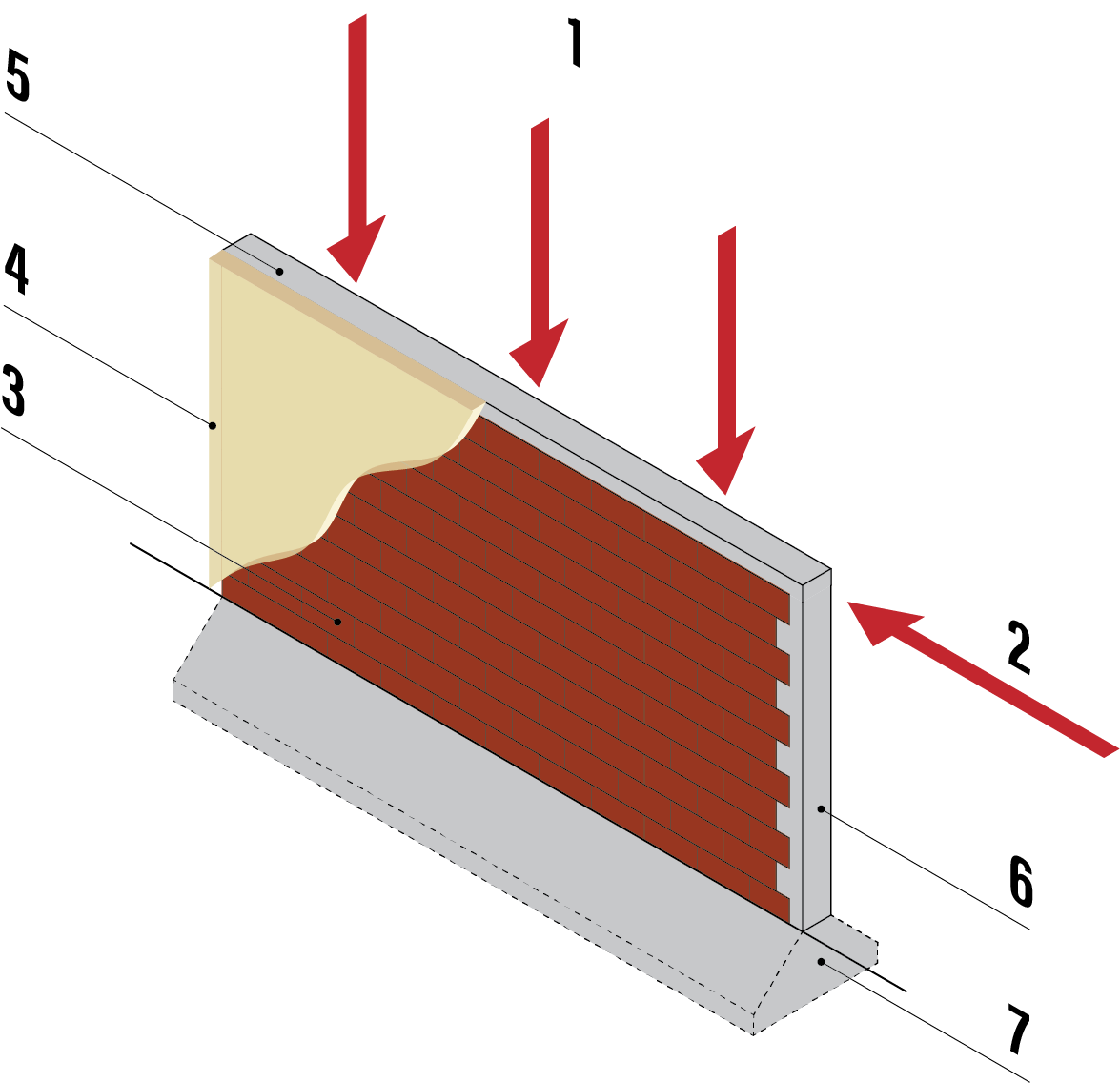
Figure 1. A wall is strong for downwards forces (1) and horizontal forces (from earthquakes) (2) parallel to its length. Masonry units or bricks (3) are plastered (4) and supported by a foundation (7). The masonry is confined by a tie beam (5) and practical or tie columns (6).
[Article 5: Walls during earthquakes]
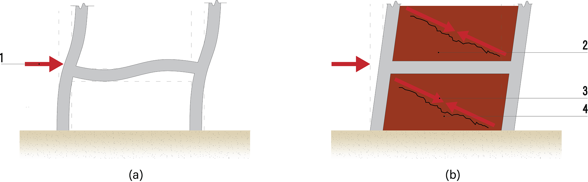
Figure 1. (a) An elevation of a bare or open column and beam frame that is bending sideways in an earthquake (1). (b) shows how the infill (2) prevents bending, experiences a diagonal compression stut (3) and diagonal cracking (4).
[Article 10: Infill Walls]
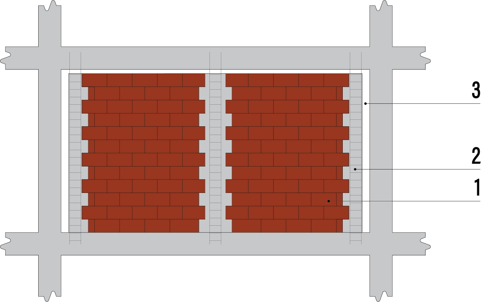
Figure 3. A masonry infill wall (1), protected from shaking perpendicular to its length by intermediate, or ‘practical columns’ (2), and separated from columns and beam by narrow gaps (3) subsequently infilled with soft material and covered with a flashing.
[Article 10: Infill Walls]
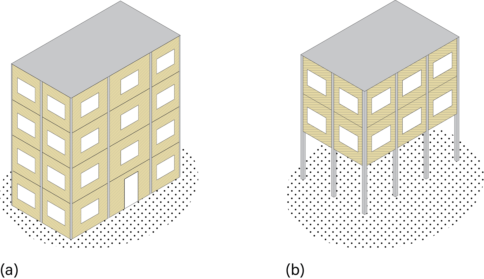
Figure 1. Two similar buildings with (b) having an open story at ground level.
[Article 11: Soft Story]
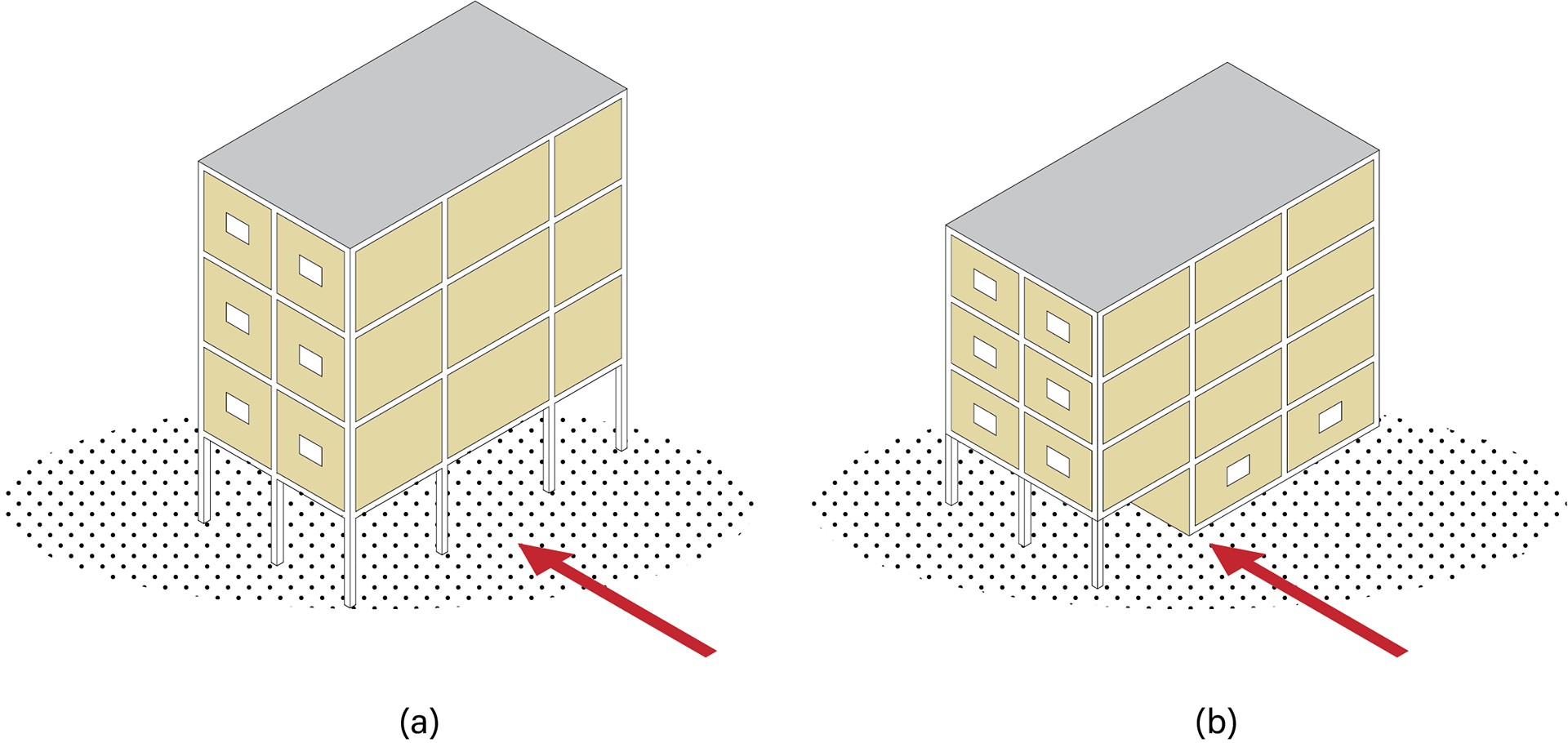
Figure 1. Two types of discontinuous walls. In (a) there are no infills at the ground floor, and in (b) the ground floor infill wall is off-set relative to the wall above.
[Article 12: Discontinuous Walls]
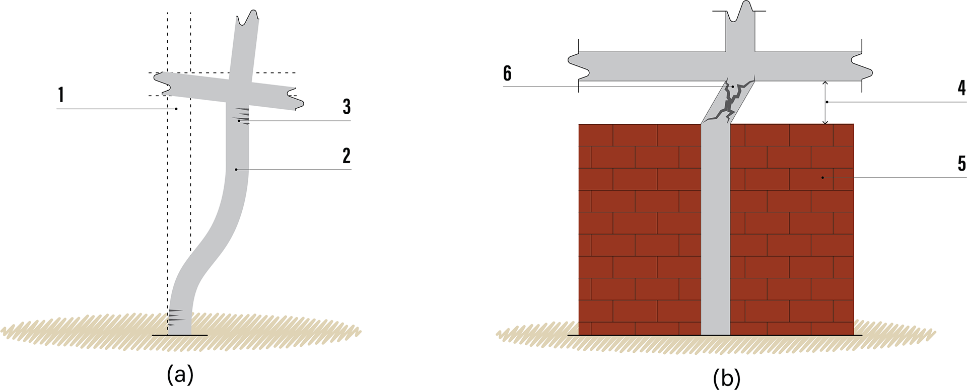
Figure 3. (a) During an earthquake (1) a normal height column bends (2) as it moves horizontally. In the process it cracks (3) but can still remain strong. In (b) an upper window (4) and masonry infills (5) cause serious diagonal cracks in the short column that lead to the column disintegrating.
[Article 13: Short Column Effect]
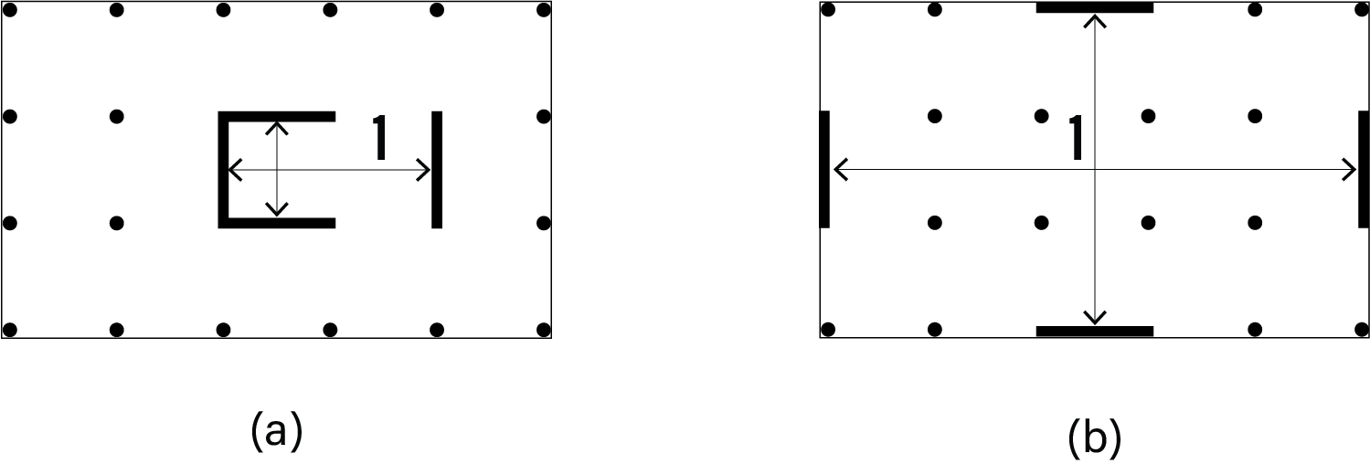
Figure 4. Two ground floor plans of buildings. In (a) earthquake forces in each direction, across and along the building, are resisted by two walls placed reasonably symmetrically. The walls are separated (1) but not by much. However, in (b) the walls acting in each direction have maximum separation (1) and so provide the best control of torsion.
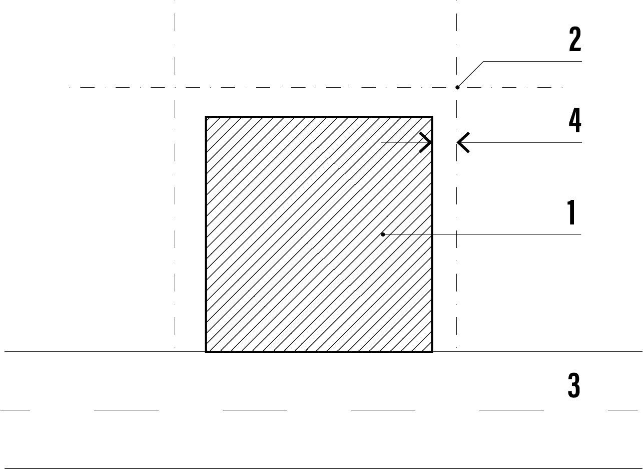
Figure 3. A plan of a building (1) within its boundaries (2) and on a street (3). On three sides the building is built back from the boundaries by the width of a seismic gap (4).
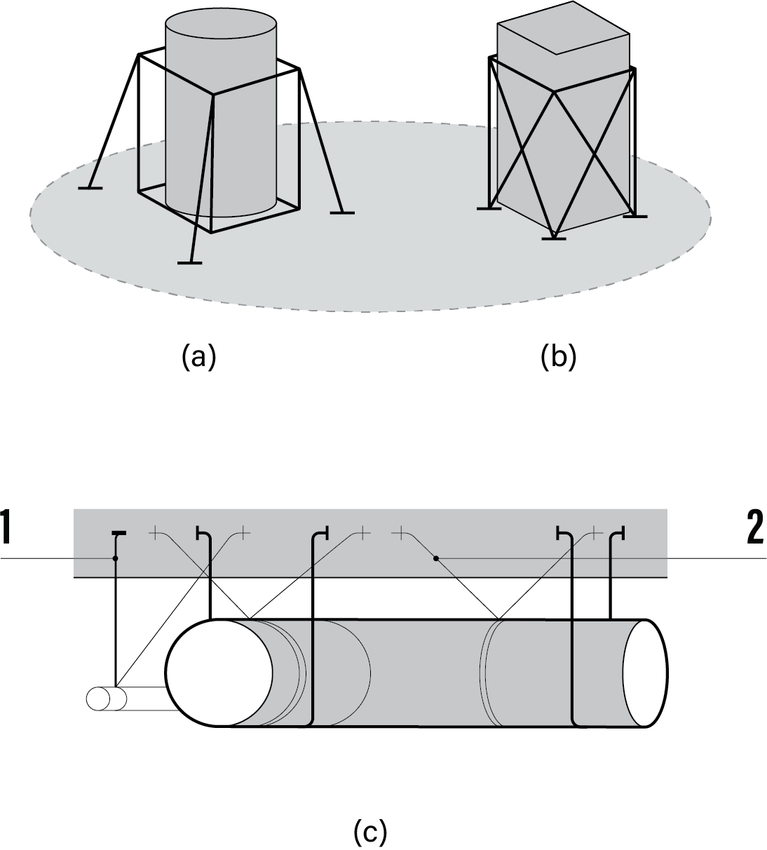
Figure 5. Tanks (a) and mechanical equipment (b) should be braced against earthquake. Also, in (c) pipework hangers (1) and ducting are braced (2).
[Article 21: Non-Structural Components]
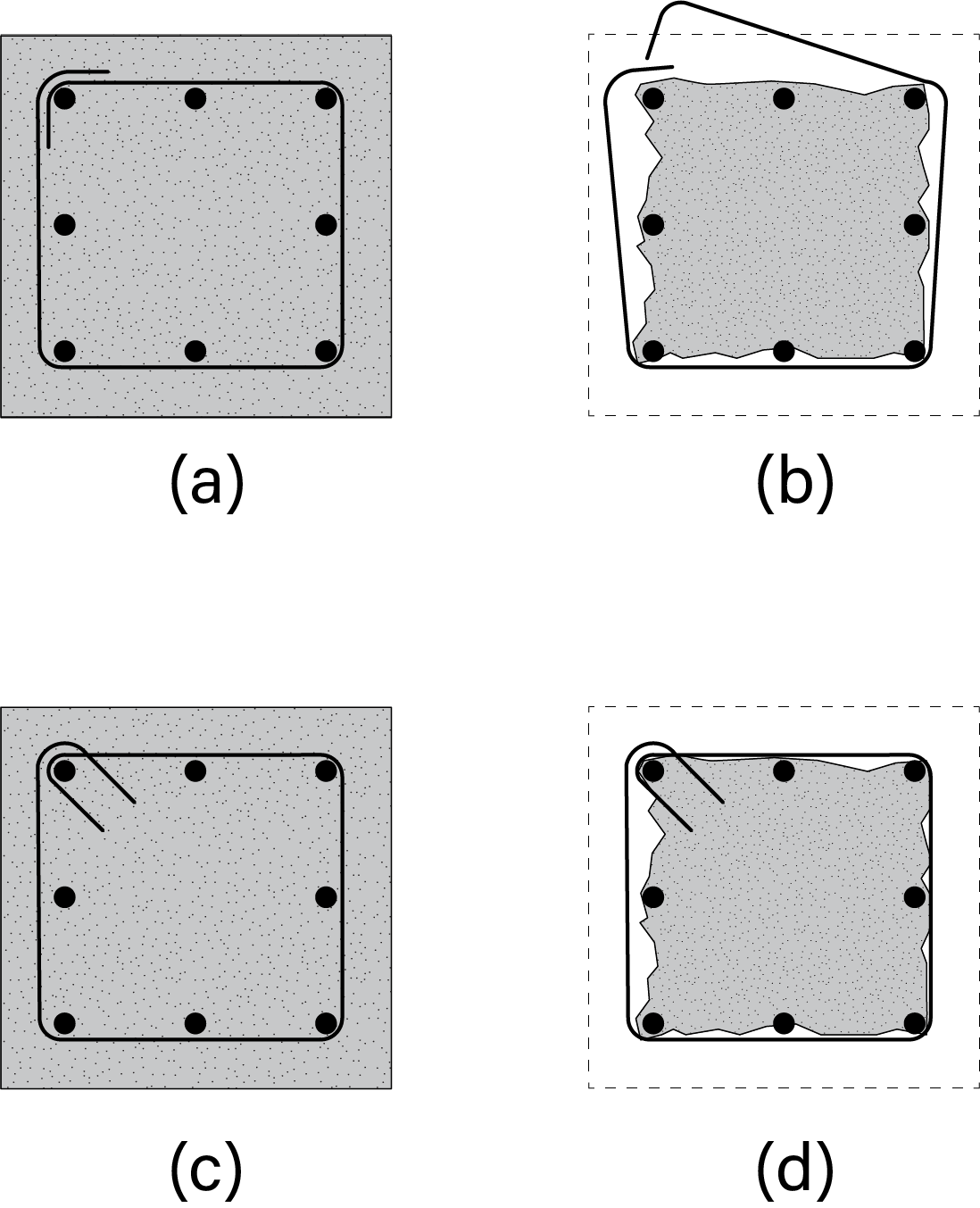
Figure 1. (a) shows a column cross-section where the ties have only a 90 degree bend. When the column is inevitably damaged during an earthquake, the bend just opens out and the tie is useless (b). In (c) the tie has been bent properly, and in accordance with code, with a 135 degree bend. When the column is damaged the tie is still effective (d).
[Article 22: Retrofitting Buildings]
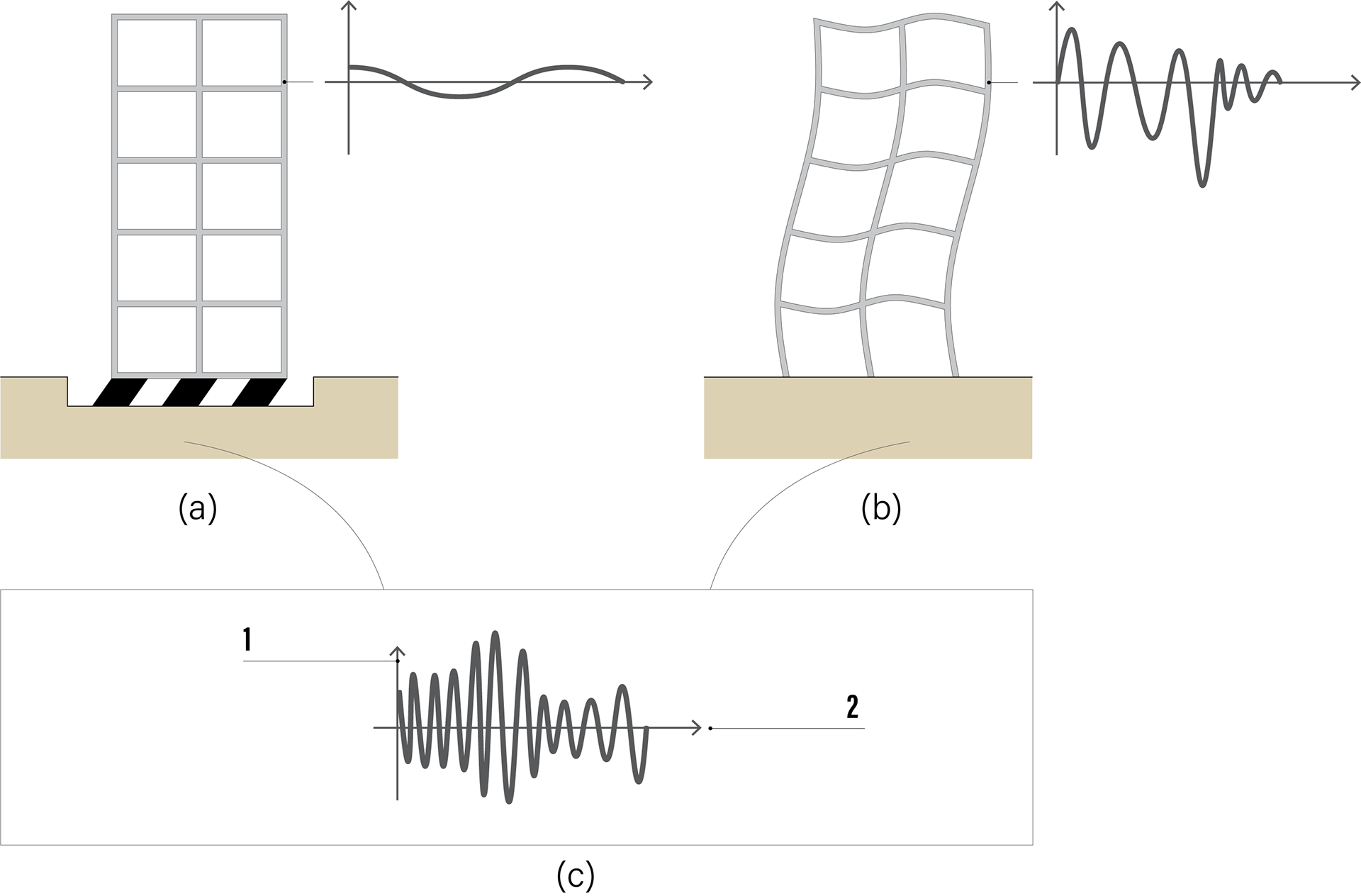
Figure 1. (a) A base-isolated building moves as a whole above its bearings while (b) shows how a conventional building bends up its height. Both buildings experience an earthquake record (c) where (1) is acceleration and (2) is time. Notice how the shaking in (a) is less and gentler than that of (b).
[Article 23: Advanced Earthquake Resiliency Approaches]
[Article 23: Advanced Earthquake Resiliency Approaches]

Figure 4. A frame building of columns and beams (1) with dampers (2) at the tops of diagonal braces (3).
[Article 23: Advanced Earthquake Resiliency Approaches]
[Article 23: Advanced Earthquake Resiliency Approaches]
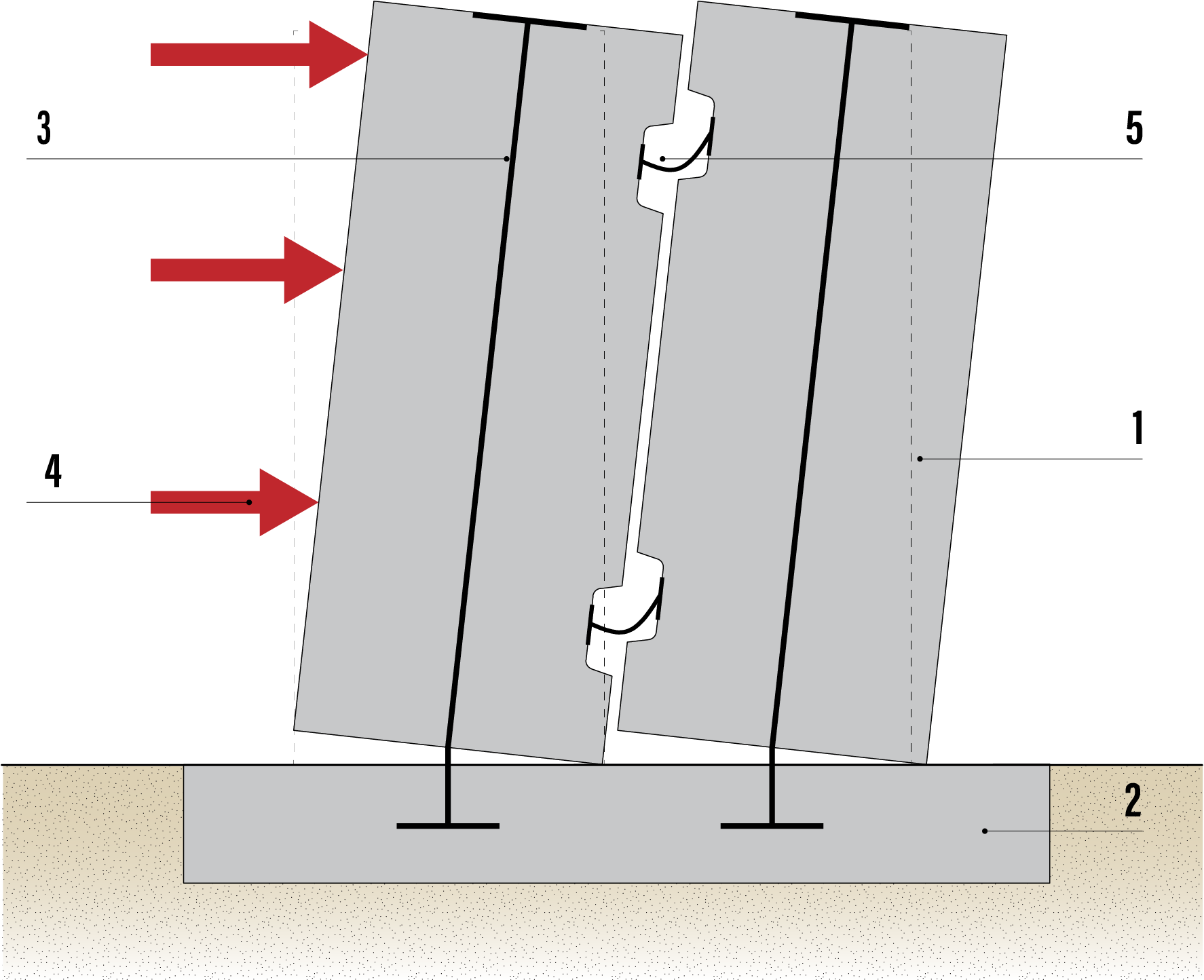
Figure 6. Two concrete walls side by side (1) connected to the foundations (2) by steel tendons (3) which stretch during earthquake loads (4). Steel plates (5) are distorted, absorbing energy and reducing resonance.
[[Article 23: Advanced Earthquake Resiliency Approaches]